
1.1 System network structure
The network architecture of MACS-K system consists of three parts, from top to bottom, management network (MNET), system network (SNET), and control network (CNET). The system network and control network are redundant, and the management network is optional. The system network architecture diagram is as follows:
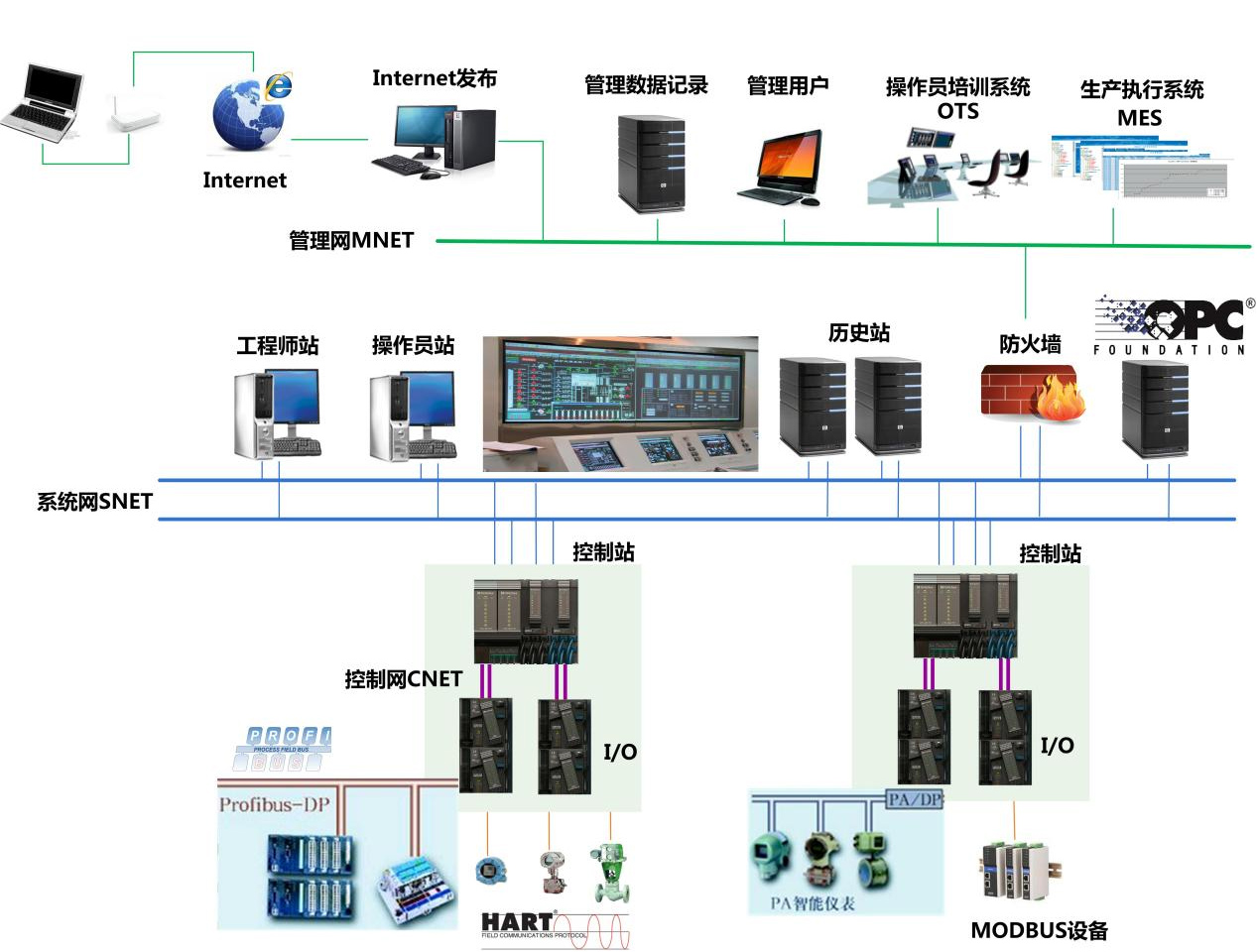
Figure 01 System network architecture diagram
n Management Network (MNET)
It is composed of 100/1000M Ethernet network, which is used for communication between the control system server and the factory-level information management system (RealMIS or ERP), the INTERNET, third-party management software, etc., to achieve advanced management and sharing of data. The management network layer is optional.
n System Network (SNET)
It is composed of 100/1000M high-speed redundant industrial Ethernet network, which is used for the connection of engineer station, operation station, field control station and communication control station, and complete the data loading of field control station. Can quickly build star, ring or bus topology of high-speed redundant security network, in line with IEEE802.3 and IEEE802.3U standards, based on TCP/IP communication protocol, communication rate 100/1000Mbps adaptive, transmission medium with RJ45 connector type 5 unshielded twisted pair.
n Control Network (CNET)
Redundant fieldbuses are used to connect various I/O modules and smart devices, supporting both star and bus networks for the first time. Real-time, fast and efficient completion of field communication tasks, in line with IEC61158 international standards (national standard: JB/T10302.3-2001/ European standard: EN50170, that is, PROFIBUS-DP communication protocol), the transmission medium is shielded twisted pair or optical cable. In the MACS-K system, we also call the control network IO-BUS.
1.2 Function description of system network and control network nodes
The network node of the system network is mainly composed of engineer station, operator station, history station (optional can double as system server), control station and other components. The network node of the control network is composed of the control station and the I/O module.
n Engineer Station
Used to complete system configuration, modification and installation, including: database, graphics, control algorithm, report configuration, parameter configuration, operator station, field control station and process I/O module configuration, data installation and incremental installation.
n Operator station
Used for monitoring and management of production site, including: centralized management and monitoring of system data, process flow chart display, report printing, control operation, historical trend display, log, alarm record and management.
n Historical Station (Optional double system server)
It is used to complete the system historical data service and exchange information with the factory management network.
n Control station
Used to complete the field signal acquisition, control and interlock control algorithm, control output, data and diagnosis through the system network to the operator station and other functions.
n I/O module
Used to convert analog signals to digital signals, engineering unit conversion, module and channel level fault diagnosis. It is sent to the main controller unit via a redundant multifunction bus.
Table 1-1 lists the performance specifications of the HOLLiAS MACS-K system.
System performance index | |
System scale | |
Supports a maximum of 15 domains | |
Single-domain ****** scale | |
Historical number of stations | Two sets |
Field control station | sixty-four |
Operator station | 64 units (including 2 redundant history stations that can double as operator stations) |
The number of operating stations that communicate directly with the master | sixteen |
****** internal point of analog quantity | 26000 |
****** analog input point | 8000 |
****** switch quantity internal point | 26000 |
****** switching input point | 14000 |
******DCS device points | 6000 |
****** pulse quantity input point | 6000 |
******SOE | 2000 |
****** switching output point | 8000 |
****** analog output point | 6000 |
Single field control station ****** scale | |
Number of I/O modules | 100 yuan |
Physical I/O configuration capability | 1280 points |
AI points | 640 (including pulse volume, thermal resistance, thermocouple signal) |
AO number | 240 |
DI points | 1200 |
DO number | 1200 |
Control the number of circuits | 300 |
The analog quantity controls the number of circuits | 128 |
Actual corresponding capability | |
From input change to display the change time | <1s |
Change time from operation typing to corresponding output | <1s |
Event sequence recording resolution SOE | 0.1ms |
The CPU controls the IEC cycle | 50ms, 100ms, 200ms, 500ms, 1s |
Minimum response time of input-output loop | < 100ms (IEC cycle is 50ms); < 200ms (IEC cycle is 100ms, default); |
The screen shows the completion time | ≤1s |
Dynamic data update time | ≤1s |
MACS system products are CE certified, that is, fully compliant with EU EMC requirements.
Table 1-1 MACS system performance specifications
HOLLiAS MACS system hardware improves the reliability and ease of use, and applies a variety of redundancy technologies to ensure the safe and reliable operation of the system hardware. From the perspective of user experience, it has the characteristics of easy to use, easy to change and easy to maintain.
n Control network Network structure
The main hardware of HOLLiAS MACS system is composed of controller module and I/O module. The controller module is the hub between the system network and the control network. The bus module is the hub that connects the controller to the I/O module. The CNET connection diagram of the control network is shown in Figure1-2.
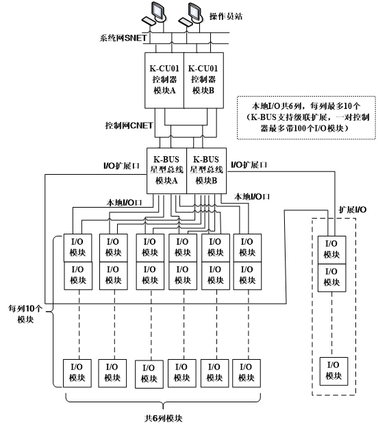
Figure 12 CNET connection schematic diagram of control network
Up to 6 rows of DIN35 guide rails can be installed in a single cabinet, and up to 10 I/O modules can be installed on each guide rail. K-BUS supports cascading expansion. A pair of controllers has a maximum of 100 I/O units.
n Install hardware on the onsite control station
The HOLLiAS MACS hardware is modular and can be installed in any cabinet using DIN35 standard rails.
n Field control station cabinet
? Cabinet type: Control cabinet/control expansion cabinet
? Size: 2200×800×800mm (height × width × depth)
? Color: international standard RAL7032 or RAL7035, etc
? Material: Steel plate, box frame, top cover, back wall and bottom plate: 1.5mm. Door: 2.0mm.
? Surface treatment: box frame (dip primer); Door, top and back wall (dip primer, powder coating on exterior); Mounting plate and base plate (galvanized).
Protection class: IP56, according to EN60 529/03.2000, in accordance with the requirements of NEMA 12.
Figure 1-3 shows the cabinet.
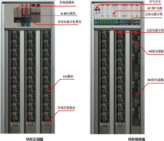
Figure 13 Cabinet layout
n System Capacity
The hardware devices (backplane, main control, I/O unit, power supply, base, and terminal board) of the K series are centrally installed in the cabinet and connected through special cables and conductors. A maximum of 10 I/O modules can be installed in each column. The length of the I/O module base is 120mm, and the length of the redundant base is 240mm. The length of the terminal board is 200mm and 300mm.
K series Number of modules installed in a single cabinet ******
Topological structure | Main cabinet | Extension cabinet | total |
Bus shape | 30 | 0 | 30 |
Star + bus | 60 | 30 | 90 |
star | 60 | 40 | 100 |
1. When the IO-BUS network adopts the bus configuration: a single control station ****** supports only 30 I/O modules, which are installed on the guide rails (bus ports) in columns 1 to 3.
2. When the IO-BUS network is configured in star configuration: a single controller station and a single cabinet are limited by physical space ****** supports 60 I/O modules. The system performance is limited by expansion cabinets ****** Supports 100 I/O modules.
n Controller unit
The controller adopts the backplane + module design. Two controllers and two control network connection modules (IO-BUS) can be inserted into one controller backplane.
The controller unit is generally installed in the upper part of the cabinet. It can be installed by rail or screw, and can even be directly hung in the wall-mounted box. It is very convenient to install and disassemble, small in size, and saves the space in the cabinet.
The controller backplane connects to the I/O module through prefabricated cables. It supplies power to the I/O module and provides communication channels. The upper end plug of the prefabricated cable for each column corresponds to the multifunctional bus port on the controller backplane, and the redundant prefabricated cable for the module in column n corresponds to An Bn multifunctional bus port. Each cabinet can house a maximum of six columns of modules, that is, the value of n is 1 to 6.
Figure 1-4 shows the appearance of a 4-slot controller
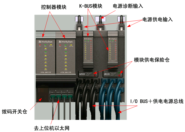
Interface diagram of the 4-slot controller unit
n IO-BUS module
The IO-BUS module is used to implement bus or star connections. BUS module has the function of hub, which can change the topology structure of the network and realize the transformation of the network topology from the bus network to the complex network structure such as star and tree.
n I/O module
K series module adopts dual redundant communication IO-BUS bus and dual redundant power supply working mode. If an IO-BUS and power supply are disconnected, normal operation will not be affected. The K system module also uses the field power supply and the system power supply separately and isolated. The circuit connected to the instrument is powered by the field power supply, and the digital circuit and communication circuit are powered by the system power supply, so the field interference will not affect the digital circuit and communication. K series modules All modules can be electrically pluggable.
The complete module unit of a K-series module consists of an I/O module, a module base and two power IO-BUS buses. The I/O module is plugged into the I/O base. The terminal of the K-series module base is responsible for connecting to the field instrument signal, and the I/O module is responsible for converting the analog signal to digital signal. Finally, it is sent to the master unit through the redundant multifunction bus. Figure 1-5 shows the installation position of a complete module in the system cabinet.
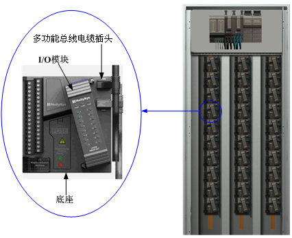
I/O module unit diagram